| Robot
Probes |
Earthlings should appreciate this since most of your space
exploration is currently undertaken by robots! Now, suppose we
want a probe to explore a planet - what design would we
choose? Often it's not just the surface of a planet we want to
explore, but the subsurface. On a harsh planet like Mars, it may
well be that beneath the soil is a layer of ice and beneath that
there might just be seas of liquid water. To explore such a world
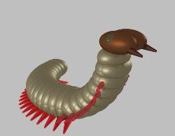
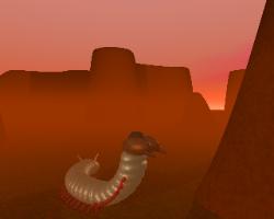
we might choose a robot capable of burrowing. Worms make
good efficient burrowers, so let's make our probe worm-like.
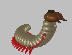
they don't get in the way when the probe is burrowing. With short legs we may need a lot of them to
generate stable thrust, so now our probe looks a bit like a millipede or a velvet worm. We could even make
theses leg-like appendages flattened and paddle-like, so that our probe can swim well in and under liquids,
rather like a rag-worm. We can equip the leg-like podia and perhaps the under-surface of the probe with
fields of microscopic recurved hooks to provide traction to enable the probe to crawl over smooth surfaces,
or even up and over vertical barriers. For very smooth surfaces, which prevent the hooks gripping, hollow
hair-like structures can exude a glue-like substance to assist traction. The hairs can be so designed such
that they will only detach easily if moved forwards, but grip if dragged backwards (rather like the foot-pads
of certain frogs).
We need some sensors, not only so the probe can get about, but so that it can collect valuable data about
its surroundings. Let's give it a pair of eyes that can see visible light, ultraviolet and infrared. We can use
these sensors to record daily fluctuations in light levels and to search for life-forms that may radiate heat. It
could have polarised ultraviolet vision to locate the parent star or stars, even when the weather is cloudy.
which consists of six petal-like valves that open out. Through this
an excavator tool can be protruded - perhaps a drill or crushing
jaws to remove hard rocks. In soft sediments our probe could
probably dig without this, by simply wriggling through the soil and
using its many appendages to push the soil behind it as it
burrows. The excavator could contain an aperture to ingest
ground soil particles into the probe for analysis, perhaps after
grinding them to a fine powder. Note the two conical
protuberances at the front of the head - these are probes which
can take in soil and water for analysis.
analysis, some of the particles may pass into a miniaturised scanning electron microscope (SEM) inside
the probe. This microscope will scan for microscopic life-forms and can also perform an X-ray analysis of
selected areas of the sample surface to determine the elemental composition of the material. It is also
equipped with an ion-beam to etch away the surface of the sample and probe deeper. A miniaturised mass
spectrometer is also attached for additional analysis of the molecular structure of the sample.
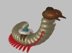
bio-reaction chamber in which soil or liquid samples can be
incubated under various conditions of temperature, light and
nutrient provision. It is not necessary to carry these modules all
the top and so they are detachable. Another useful module is the
atmospheric analysis module. The probe has a mobile tail with
petal-like valves that open to reveal a series of manipulators
which allows the probe to manipulate items, attaching or
detaching these additional modules and operating them.
atmospheric module down into a valley and place it in a sheltered crevice to monitor due formation. Note
that these modules must be removed prior to any burrowing operation. The eyes can also be withdrawn
into the head and closed by heavy shutters to protect these sensors during digging operations. Digging
through ice is particularly difficult since ice is a very resilient material, so perhaps the excavator unit shoul
be able to generate heat, perhaps with the help of a laser beam.
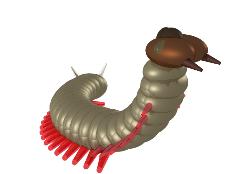
segment. These would need to be retractable, so they can be
withdrawn for their protection during excavations. When deep
beneath the surface the probe will most unlikely be unable to
return data by direct transmission, so it will have to store the
data in its memory banks, but what if it gets trapped? It could
lose valuable data. Well, from the rear end it can release a tiny
worm-like crawler from inside itself.
and tunnel itself back to the surface by retracing the route the probe took. Having so simple a task it can
be much miniaturised, making it far less likely to get trapped by collapse of the burrow. The probe could
also shore up the burrow, perhaps by lining it with mucus-like or silk-like material as it goes. More often
than not though, it would be easier to send it down and wait until it manages to dig itself back to the
surface, by whatever route it can find! It can use its infra-sound emitter and vibration sensor to probe the
substrate in front of it for harder materials and avoid these. The probe will have to be able to act
intelligently by itself, since it may be cut off from base for quite some time. It has a powerful computer
brain, of course. It would also need to be very robust. It's components are impact resistant, so it won't fail
should it miss a couple of steps like ASIMO did. It also has sophisticated systems to locate internal faults
and carry out limited repairs. Powering such a probe would be an immense problem for Earthling
technology. The SEM alone requires a few thousand volts of electricity. We could have a power cell in
each segment and then connect them in series, or we could go for something a bit more sophisticated, like
a nuclear reactor or an anti-matter annihilator.
planet's surface. The capsule opposite relies initially on
parachutes to slow its descent through the atmosphere and
then the chutes detach and when it impacts the surface at a
much reduced speed, it bounces on its twelve shock-absorbers,
which are made of the latest elastic materials, adjusted with the
correct spring stiffness for the local gravity of the planet. On
high gravity worlds, air bags could also be deployed. The
capsule is an icosahedron with 20 faces. Each face can be
opened and our intelligent probe, coiled up in a central
chamber attached to the edges and vertices of the icosahedral
shell can use its gravity sensors to determine which way up it
has landed and select whichever of the 20 exits is most
convenient and crawl out from the capsule.
driven micro-satellite capable of returning small soil samples to planetary orbit for later collection. The
microwave beam is fired from the ground and propels the micro-satellite upwards at tremendous
accelerations to escape the planet's gravity. The capsule can also contain a more powerful data
transmitter should the data need to be transmitted across interplanetary or interstellar space. If a receiver
is located in orbit, then the antennae on the probe itself should prove sufficient, but should these fail then
the probe can upload its data to the capsule for storage or transmittance.
we have received unconfirmed reports of relics of an ancient
and seemingly extinct civilisation on this world...
use to explore such a world?
geosensors that map the underlying substrates using thermal conductivity and spectrum analysers.
Retractable arms can collect samples for analysis by internal instruments, including scanning electron / ion
beam microscopy and UV elemental analysis. A telescopic drill can drill to a depth of 40 metres for initial
strata sampling.
